Backbone Site Hardware: Difference between revisions
No edit summary |
No edit summary |
||
| Line 58: | Line 58: | ||
==== VLANs ==== |
==== VLANs ==== |
||
[[File:TypicalHardwareVLANs.png|none|thumb|600x600px]] |
[[File:TypicalHardwareVLANs.png|none|thumb|600x600px]] |
||
| − | We configure the router to use a single, VLAN aware bridge. In this configuration we can control which VLANs on which ports are connected. Because the bridge is VLAN aware, traffic on different VLAN is never merged. |
+ | We configure the router to use a single, VLAN aware bridge. In this configuration we can control which VLANs on which ports are connected. Because the bridge is VLAN aware, traffic on different VLAN is never merged. You access this configuration using the Action drop down associated with ''switch0''. |
* By default, we allow VLAN 2 - the AREDN DtD VLAN - to pass to every port except ''eth0''. |
* By default, we allow VLAN 2 - the AREDN DtD VLAN - to pass to every port except ''eth0''. |
||
| − | * VLAN 1100 - the XLINK VLAN - is passed to ports ''eth0'' (the airFiber) and ''eth4'' (the hAP). |
+ | * VLAN 1100 - the XLINK VLAN - is passed to ports ''eth0'' (the airFiber) and ''eth4'' (the hAP). This allows the xlink traffic from the hAP to flow in and out of the airFiber radio. |
At specific sites, this configuration is often changed to support additional backbone radios and additional XLINKs. |
At specific sites, this configuration is often changed to support additional backbone radios and additional XLINKs. |
||
==== OSPF ==== |
==== OSPF ==== |
||
| + | [[File:TypicalHardwareOSPF.png|none|thumb|600x600px]] |
||
| − | ... |
||
| + | [[wikipedia:Open_Shortest_Path_First|OSPF]] is the protocol we use to manage the backbone network. An extensive explanation of this protocol is beyond the goal of this. Here we'll just highlight our configuration. |
||
| + | |||
| + | * The ''Router ID'' (top left) is the unique ID of each router in the network. The ID looks suspiciously like an IPv4 address, and although it isn't; it usually has some relationship to the IPv4 addresses associated with the device. |
||
| + | * ''Redistribute static'' (top middle) is checked. If we later defined a public IP address on this device, this option will make sure the rest of the network can route traffic to it. |
||
| + | * |
||
==== Public IP Delivery ==== |
==== Public IP Delivery ==== |
||
Revision as of 12:12, 7 November 2023
We had tried to standardize hardware at sites where we can. This simplified management and maintenance.
Hardware
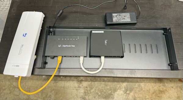
The image belows illustrates the basic hardware we would install at a backbone site.
This consists of the following components:
- An Ubiquiti EdgeRouter X SFP which supports the backbone routing protocols, as well as providing power-over-ethernet to the other components
- A Mikrotik hAP ac2 which provides AREDN services at the site
- An Ubiquiti airFiber radio which connects this site to others in the network
- A 19" rack shelf to install the hardware on.
- 24v power input, either from an AC/DC converter, or from a battery backup supply (not shown here)
Connections
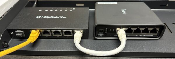
By using a PoE router, we simplify the wiring of the rest of the system as every other component is powered over ethernet.
- The white cable on the right provides networking and power to the hAP.
- The yellow cable on the left provides power and networking to the airFiber radio.
- Additional backbone devices can use the additional three ports on the router (with appropriate configuration - see below)
- Additional AREDN devices can use either the additional router ports or the hAP ports (with appropriate configuration - see below)
Configuration
Both the hAP and the Router require custom configuration.
hAP ac2 Configuration
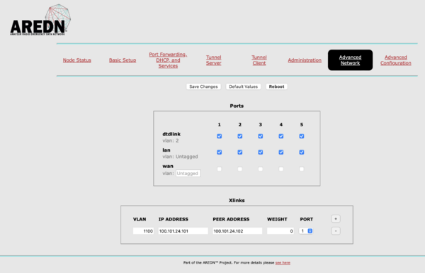
The hAP is configured just like any other AREDN nodes; but there are a few changes in the Advanced Network tab.
Ports
- All the ports, 1 through 5, are configured as both AREDN LAN and AREDN DtD ports. This gives us a lot of flexibility in what devices we can attached to the node later.
- We have no WAN ports selected as we dont use any local Internet services at sites.
- Port 1 is the PoE-IN port. This configuration lets us power the hAP with PoE.
XLinks
The basic configuration uses one xlink to connect this AREDN device to others over the airFiber radio. More information about xlinks can be found in the AREDN documentation. In this configuration:
- We use VLAN 1100. XLink data is always encapsulated with a VLAN, and for backbone traffic we use VLANs starting at 1100.
- Port 1 is selected - the same port providing power, DtD and everything else to the hAP from the Router.
EdgeRouter X SFP Configuration
The EdgeRouter performs multiple roles in this setup:
- It provides power to everything else.
- It routes AREDN DtD and LAN traffic to its physical ports.
- It routes XLINK traffic from the hAP to the airFiber radio.
- It manages its part in the backbone using OSPF.
- It enables the delivery of public Internet IPv4 or IPv6 address endpoints to this site.
Power-over-ethernet
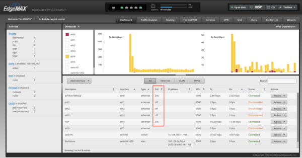
The Power-over-Ethernet setting is configurable per port. In the above you can see which ports are enabled (inside the red box).
The PoE setting is controlled by the Action dropdown to the right of the screen.
VLANs
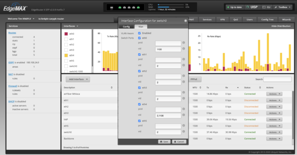
We configure the router to use a single, VLAN aware bridge. In this configuration we can control which VLANs on which ports are connected. Because the bridge is VLAN aware, traffic on different VLAN is never merged. You access this configuration using the Action drop down associated with switch0.
- By default, we allow VLAN 2 - the AREDN DtD VLAN - to pass to every port except eth0.
- VLAN 1100 - the XLINK VLAN - is passed to ports eth0 (the airFiber) and eth4 (the hAP). This allows the xlink traffic from the hAP to flow in and out of the airFiber radio.
At specific sites, this configuration is often changed to support additional backbone radios and additional XLINKs.
OSPF
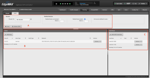
OSPF is the protocol we use to manage the backbone network. An extensive explanation of this protocol is beyond the goal of this. Here we'll just highlight our configuration.
- The Router ID (top left) is the unique ID of each router in the network. The ID looks suspiciously like an IPv4 address, and although it isn't; it usually has some relationship to the IPv4 addresses associated with the device.
- Redistribute static (top middle) is checked. If we later defined a public IP address on this device, this option will make sure the rest of the network can route traffic to it.
Public IP Delivery
...
