Power-over-Ethernet
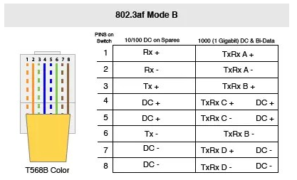
This Wiki dosn't accurately describe the way Ubiquity deploys PoE Expect to encounter mode B on the T568B wiring standard for data over an 8wire / 4pair Cat 5e utp cable.
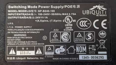
All of the AirMax and GL.iNet class devices have 100Mbps Ethernet ports. They receive power via that Ethernet port as well. 24V DC is sent over the cat 5e line. The DC voltage is injected on "spare pairs" unused by 100Mbps Ethernet. A fixed DC voltage is provided (positive voltage to pins 4- 5) and (negative voltage to pins 7-8.
GB-B240-100
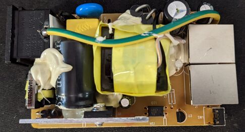
This is a black 1 amp 100Mbps injector. Its not possible to obtain 1000Mbps port speed with a GB-B240-100, pins 4- 5 and pins 7-8 have been observe to no be connected on the LAN side of the injector.
GB-A240-050
This is a black .5 amp 100Mbps injector. Note the reset
Don't forget the white model
This is a white .5 amp 1000Mbps injector.
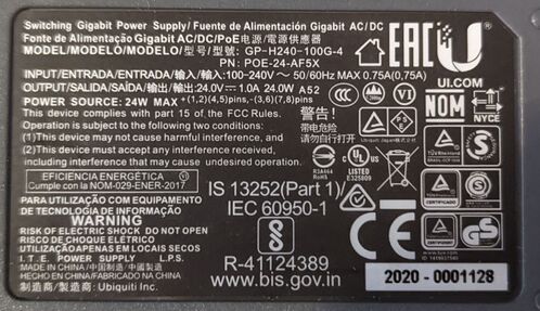
GB-H240-100-4
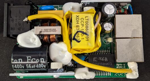
You might ask... How do devices running at 1000Mbps Ethernet ports receive PoE? The G24102HKG chip is how! Data sheet 26528.pdf. 
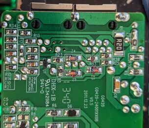
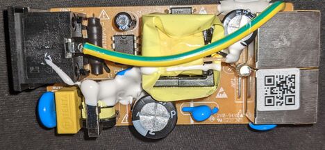
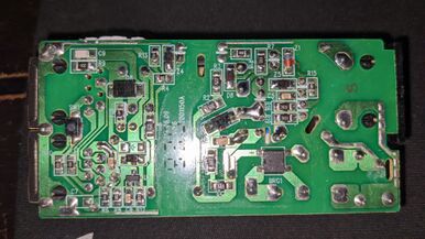
This is a gray 1 amp 1000Mbps injector. Power is sent over all 4 pairs with data. The injector are found in the box of AirFiberX and AC-Gen2 devices. Its a Passive 1000Mbps PoE injector as well.
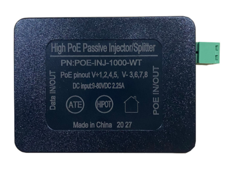
Tycon Power Systems POE-INJ-1000-WT Gigabit PoE Injector/Splitter 4 Pair
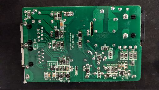
This is a Gigabit PoE Injector. This injector breaks in or out power, all 4 pairs are isolating allowing for 1000Mbps Ethernet speeds. Unlike the Ubiquity injectors you must supply a power source.
Caution! Connecting any passive or active 48v DC PoE source to a passive device will damage a passive device!
Great article that parallel my interest with POE.
Nanoswitch N-SW
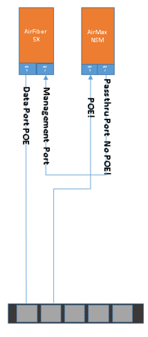
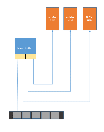
The N-SW is marketed as a 2 pair passive PoE powered, unmanned 4 port 10/100/1000 Mbps Ethernet RJ45 switch. The device is intend for outdoor use. Thanks to W2GMD for discovering that the N-SW accepts 4 pair passive 24v DC on the input port. The N-SW is allows one to "breakout" devices from a single cat5e cable. We commonly used them to run 2 or 3 devices off of a single cat5e run to the top of a tower. This is where we start to run in to the problems...
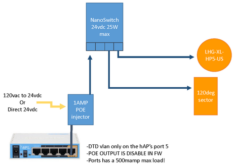
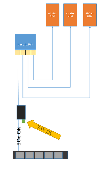
The following diagram describes how to properly power a N-SW, off of a hAP. The hAP wasn't designed to deliver more than 500mA of current at the port.
The fuse limits are independent from the input voltage 9-24v on a hAP! As result of not using an external injector to supply power to the N-SW with 2 breakout devices, the devices down stream of the hAP's port 5 will brown-out causing the devices to reboot!
NOTE! How Ubiquity devices react when supplied insufficient input power!
Device get can get stuck in reboot loops, if every thing is just right! As the load increases --> The supply voltage falls --> current limits trips --> Device reboots. It turns out that Airfiber is very sensitive! AirMax equipment too!
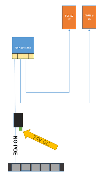
The nanoswitch accept 4pair passive poe and 2pair passive poe for power. Then we have 3 types of devices being powered... one type runs 2 pair passive 24v poe and runs at 1Gb port speed. Two a device that runs on 4 pair passive 24v poe runs at 1Gb, and the most common 2 pair passive 24v poe running at 100Mb. 1Gb devices have power isolation on all 4pairs but may only pull from 2 pairs! Ive found that for an AirFiber3x device to reach full tx power levels while sharing a Nanoswitch with another 2 pair device the Nanoswitch needs to be feed 4pair passive 24v power.
