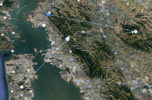
Bay Area Backbone
The Bay Area Backbone Project is building solid, fast, links between major high sites in the Bay Area, which in turn supports a more stable mesh network. We do this for a number of reasons:
- It easier to connect high sites to other high sites, especially when we're trying to connect different neighborhoods while avoiding mountain ridges.
- High sites are often backed up with generator power. We provide battery backup ourselves, but that will only last so long.
- High sites will be thee when the Ham moves on. Because these are generally commercial sites with long histories of ham involvement, we are not a the whims of someones current housing situation or - in some cases - employment situation.
- It's often easier for a neighborhood to connect up to a high site (or more than one) as they're less obstructed.
Status
The current health of the backbone is monitored here (internet)
Management VLANs
Each site manages its devices on a unique VLAN to isolate them from all other sites (the management VLAN is not passed across any links).
| VLAN | Site | Notes |
|---|---|---|
| 3 | Fish Ranch | VLAN is not set on the AF radio |
| 3 | ORCA | |
| 121 | Mount Diablo | |
| 100 | San Bruno (Building 4) | |
| 100 | San Bruno (Building 7) | |
| 110 | Oxford | |
| 122 | CCCC | |
| 1001 | San Carlos | |
| 1003 | San Pedro | |
| 1004 | Sunol Ridge | |
| - | Wolfback | TODO |
XLINKS
XLINKS are custom VLANs between sites which feed directly into the AREDN router. Think of them as DtD links, but only point-to-point.
| Link | VLAN | Subnet | A | B | Notes |
|---|---|---|---|---|---|
| San Bruno Mountain to Swallow | 10 | 100.64.0.20/30 | 100.64.0.21 | 100.64.0.22 | |
| ORCA to Wolfback | 11 | 100.64.0.16/30 | 100.64.0.17 | 100.64.0.18 | |
| ORCA to Fish Ranch | 12 | 100.64.0.12/30 | 100.64.0.13 | 100.64.0.14 | |
| Fish Ranch to San Bruno Mountain | 13 | 100.64.0.8/30 | 100.64.0.10 | 100.64.0.9 | |
| San Carlos to Sunol Ridge | 14 | 100.64.0.4/30 | 100.64.0.6 | 100.64.0.5 | |
| San Bruno Mountain to San Carlos | 15 | 100.64.0.0/30 | 100.64.0.1 | 100.64.0.2 | |
| San Bruno Mountain to Fire Station 8 | 16 | 100.64.0.24/30 | 100.64.0.25 | 100.64.0.26 | |
| Fire Station 8 to Mount Allison | 17 | 100.64.0.28/30 | 100.64.0.29 | 100.64.0.30 | |
| Oxford to Wolfback | 18 | 100.64.0.32/30 | 100.64.0.33 | 100.64.0.34 |
Backbone Links
Active
- Fish Ranch
- ORCA
- CCCC
- San Bruno Mountain (Building 7)
- Fish Ranch
- San Carlos
- Swallow
- San Carlos
- Sunol Ridge
- Swallow
- Mount Diablo
- Richmond Field Station
- Wolfback
- ORCA
- Oxford
- Oxford
Planned
Proposed
Backbone Network Structure
Physical
A minimal backbone endpoint consists of two pieces of hardware:
- A non-AREDN radio. We generally use Ubiquiti airFiber 5XHD radios, but this is not required; any PtP radio will work.
- A Mikrotik hAP ac2 AREDN node
The radio provides the wireless endpoint for one end of a backbone link, while the hAP links that radio into the rest of the AREDN network.
Network
To connect these PtP links into the AREDN network we use an AREDN features called XLINKS. An XLINK is a point to point VLAN with a specific VLAN number for that connection. The VLAN is integrated into the AREDN network just link any other link. You can think of it as an AREDN tunnel, but without the overhead of that mechanism or the need for an Internet connection.
Mesh
Backbone links appear in the mesh labeled as xlink but are no different from any other link in the network. We are not building a hierarchy with the backbone at the top and the rest of the mesh hanging below. But the nature of the backbone, how it connects, and the way the mesh routing protocol operates, these links will provide preferred pathways between physically distance locations. And that's the goal.
Alternatives
There are other approaches to this problem. The Lamorinda Network uses an OSPF network of license radios, and then runs AREDN as a single "site" on top of it as one of its tenants.
Previous Approach
The setup for backbone links operated a simply switching VLAN2 (DtD) between all radios. This essentially makes all AREDN nodes at each site look like they're on one ethernet segment. It was not an ideal solution which we have moved away from as the backbone has grown.
