Bay Area Backbone
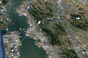
The Bay Area Backbone Project is building solid, fast, links between major high sites in the Bay Area, which in turn supports a more stable mesh network. Backbone sites are permanent locations, not dependent on amateur radio operators' homes or difficult to access places.
Status
The current health of the backbone is monitored here (internet)
Management VLANs
Each site manages its devices on a unique VLAN to isolate them from all other sites (the management VLAN is not passed across any links).
| VLAN | Site | Notes |
|---|---|---|
| 3 | Fish Ranch | VLAN is not set on the AF radio |
| 3 | ORCA | |
| 121 | Mount Diablo | |
| 100 | San Bruno (Building 4) | |
| 100 | San Bruno (Building 7) | |
| 122 | CCCC | |
| 1001 | San Carlos | |
| 1002 | Black Mountain | Not active yet |
| 1003 | San Pedro | |
| 1004 | Sunol Ridge | |
| - | Wolfback | TODO |
XLINKS
XLINKS are custom VLANs between sites which feed directly into the AREDN router. Think of them as DtD links, but only point-to-point.
| Link | VLAN | Subnet | A | B | Notes |
|---|---|---|---|---|---|
| San Bruno Mountain to Black Mountain | 11 | Proposed | |||
| ORCA to Fish Ranch | 12 | 100.64.0.12/30 | 100.64.0.13 | 100.64.0.14 | |
| Fish Ranch to San Bruno Mountain | 13 | 100.64.0.8/30 | 100.64.0.10 | 100.64.0.9 | |
| San Carlos to Sunol Ridge | 14 | 100.64.0.4/30 | 100.64.0.6 | 100.64.0.5 | |
| San Bruno Mountain to San Carlos | 15 | 100.64.0.0/30 | 100.64.0.1 | 100.64.0.2 |
Backbone Links
Active
- Fish Ranch
- ORCA
- CCCC
- San Bruno Mountain (Building 7)
- San Carlos
- Sunol Ridge
- Mount Diablo
- Richmond Field Station
- Wolfback
Planned
Proposed
Backbone Network Structure
The current set of backbone links operate simply by switching VLAN2 (DtD) between all radios. This essentially makes all AREDN nodes at each site look like they're on one ethernet segment. While sufficient for now, this is not ideal as the network increase in size.
A recent addition to the AREDN code (PR #514) allows additional VLANs (xlinks) or other network interfaces to be added to the AREDN/OLSR L3 routing layer. This enables the use of external routers and switches when building the backbone network without additional requirements on the AREDN nodes themselves.
Transitional Network Structure
We are experimenting with transitioning the VLAN2 (DtD) backbone structure to one based on unique VLANs per backbone link. Each links is integrated into AREDN using XLINKs to allow OLSR to make route selections. See "Point-to-point VLANs" below.
Possible Network Organizations
Point-to-point VLANs
One simple option is to create individual VLANs between pair of backbone radios. These VLANs are then added to an AREDN node (perhaps an hAP or similar) at each site. Topology and routing uses the current OLSR mechanism. The has the upside of being simple to implement and better than one giant shared VLAN. The downside is that this doesnt solve the routing problem for non-AREDN user of the backbone.
Fully Routed
A more complex option is to use a full routed backbone. In this case, each backbone node must contain a router with IP address. Routers have either static or preferably dynamically managed routes to pass traffic through the network. The xlink AREDN VLANs are also assigned IP addresses within this network, as well a AREDN peer IP address. The peer address need not be a directly connected node, although that probably makes most sense. AREDN will make routing choices as usual and pass traffic using the xlinks. This traffic will then be routed over the network just like any other traffic. From an AREDN perspective this is no more complex to configure that point-to-point VLANs, except that the VLANs are not exposed beyond the local router. However, the backbone network must be configured and managed separately. This has the advantage of making the backbone easily available for non-AREDN traffic.
